Edge treatments play a critical role in modern manufacturing. Whether in CNC machining, metal fabrication, woodworking, or additive manufacturing, the way an edge is finished can directly affect safety, assembly, structural integrity, cost, and aesthetics. Among the most common edge treatments are bevels and chamfers.
Although these two terms are often used interchangeably, bevels and chamfers serve different geometric, mechanical, and functional purposes. Understanding their differences is essential for designers, engineers, and manufacturers aiming to optimize performance and control production costs.
This article provides an in-depth explanation of what bevels and chamfers are, how they differ, where they are applied, and how to choose the right option for your part design.
What Is a Bevel?
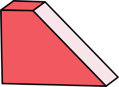
A bevel is an edge that is cut at an angle other than 90 degrees relative to the surface of the part. Unlike chamfers, bevels offer flexibility in angle selection, allowing designers to specify custom angles based on functional or structural requirements.
Bevels are commonly produced using milling, grinding, or cutting operations and are widely used where load transition, welding preparation, or visual enhancement is required.
Key Characteristics of Bevels
Sloped edge with variable angles (e.g., 30°, 45°, 60°)
Can extend along long edges or surfaces
Often used to increase contact area or improve joint strength
Suitable for both functional and decorative purposes
Common Applications of Bevels
Structural steel and welded joints
Sheet metal fabrication
Decorative furniture and glass edges
Picture frames and architectural elements
Types of Bevels in Machining
Simple Bevel – A single angled cut on one edge
Double Bevel – Angled cuts on both sides of the edge
Compound Bevel – Bevels cut at multiple angles, often for complex assemblies
What Is a Chamfer?
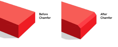
A chamfer is a flat, angled surface created by cutting away the sharp corner between two perpendicular faces. Chamfers are most commonly cut at a 45-degree angle, although other angles may be used when required by design.
Chamfering is one of the most widely applied edge treatments in machining because it improves safety, assembly ease, and part quality.
Purpose of Chamfering
Removes sharp edges and burrs
Facilitates part insertion and alignment
Prevents damage during assembly
Improves surface finish and appearance
Types of Chamfers
Inner Chamfer
Located on the inside edge of holes or cavities
Helps guide shafts, fasteners, or bearings during insertion
Outer Chamfer
Applied to external edges
Reduces sharp corners and improves handling safety
Chamfer Configurations
Single chamfer
Double chamfer
Triple chamfer
When combined, inner and outer chamfers create smooth transitions that improve both functionality and aesthetics.
Functions of Chamfering
Chamfering serves multiple mechanical and practical purposes:
Safety: Eliminates sharp edges that can cause injury
Assembly Guidance: Helps align mating parts
Burr Removal: Cleans up machining residues
Stress Reduction: Minimizes stress concentration at edges
Heat Treatment Preparation: Chamfers are often required before heat treatment to prevent cracking and deformation
In many engineering drawings, chamfers are specified not for appearance but as a mandatory requirement for proper installation and long-term reliability.
Importance of Chamfers in Agricultural Machined Parts
Agricultural machinery operates under heavy loads, vibration, dirt, and environmental exposure. Chamfers play a crucial role in:
Reducing stress concentrations on shafts and housings
Preventing crack initiation
Improving assembly efficiency in field conditions
Poorly maintained or worn chamfers can lead to:
Difficult assembly
Increased mechanical stress
Reduced equipment lifespan
Routine inspection and maintenance of chamfered edges are therefore essential in agricultural equipment.
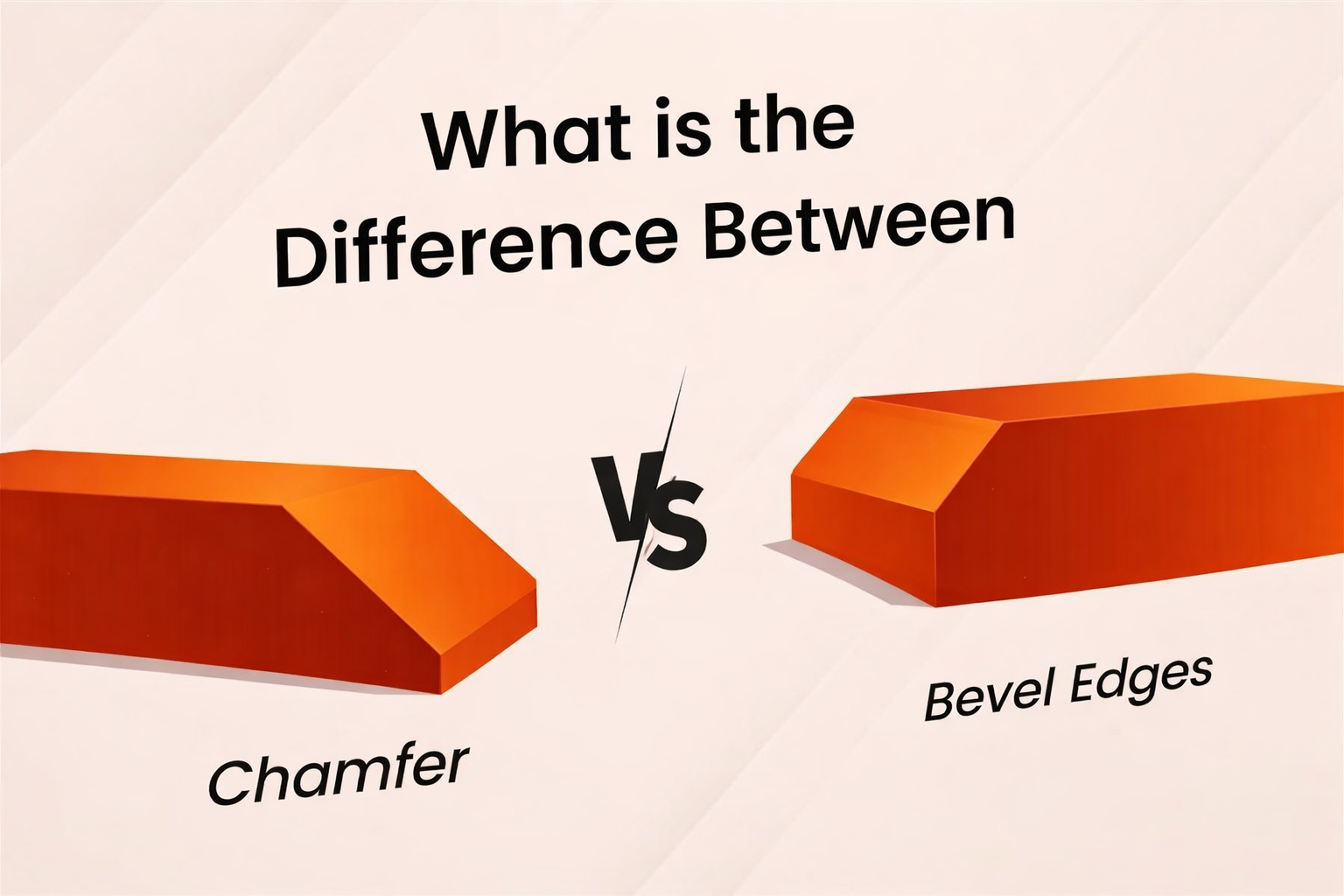
Bevel vs. Chamfer: Key Differences Explained
In mechanical design and manufacturing, bevels and chamfers are both edge treatments used to remove sharp corners. While they may appear similar at first glance, they serve different functional, structural, and manufacturing purposes. Understanding the distinction is critical for proper design intent, cost control, and part performance.
Core Difference Between Bevel and Chamfer
The primary difference lies in purpose and scale:
A chamfer is typically a small, functional edge break, most commonly at 45°, used to improve assembly, reduce burrs, and eliminate sharp edges.
A bevel is generally a larger, angled surface, often with non-45° angles, designed for structural engagement, load transfer, or welding preparation.
In short:
Chamfers support assembly and safety, while bevels support strength and structural function.
Design Intent: Functional vs. Structural
From a design perspective:
Chamfers are applied when:
Parts must align or insert smoothly
Sharp edges pose handling or safety risks
Dimensional accuracy at the edge is important
Bevels are applied when:
Edges must engage under load
Weld penetration or joint strength is required
Parts must interface at an angle
Misusing one in place of the other can lead to assembly issues, excessive machining cost, or reduced mechanical performance.
Machining and Cost Implications
Manufacturing impact is another major differentiator:
Chamfers
Easy to machine
Short cycle time
Minimal tool wear
Tight tolerances achievable
Bevels
Longer tool engagement
Often require angular control or multi-axis machining
Higher cycle time and inspection effort
As a result, chamfers are preferred in high-volume production, while bevels are reserved for function-critical features.
Tolerances and Inspection
Chamfers usually allow simple linear inspection and can hold tight tolerances.
Bevels often require angular measurement, increasing inspection complexity.
Designers should specify bevel tolerances only when functionally necessary, as over-specification increases cost without added value.
Application Comparison
| Aspect | Chamfer | Bevel |
| Typical Angle | 45° | 30°–60° (or custom) |
| Primary Purpose | Assembly & safety | Strength & structural function |
| Size | Small | Larger |
| Machining Cost | Low | Higher |
| Common Uses | Lead-ins, edge breaks | Welding, load-bearing joints |
Choosing the Right Edge Treatment
Use a chamfer when you need:
Smooth assembly
Reduced burrs
Lower cost and faster production
Use a bevel when you need:
Improved weld quality
Load distribution
Structural reliability
Practical Example: Helical Grooving on Slip Rings
In helical grooving on slip rings, chamfers are applied along groove edges to:
Reduce brush wear
Maintain smooth electrical contact
Improve operational stability
Typical Specifications:
Chamfer angle: 45°
Tolerance: ±0.005 mm
Surface finish: Ra 0.4 µm
Materials: Copper or brass
In some designs, a bevel may be used on one side while a chamfer is applied on the opposite edge to balance functionality and wear resistance.
Visual Comparison of Chamfer vs. Bevel
Chamfer Characteristics
Consistent angle
Flat transition surface
Common in safety and functional applications
Bevel Characteristics
Variable angles
Sloped transition
Common in welding and decorative designs
Applications of Chamfer and Bevel
Chamfer Applications
CNC machining (shafts, gears, engine parts)
Automotive and aerospace components
Furniture edges and cabinetry
Dental implants and medical devices
Bevel Applications
Structural steel (I-beams, H-beams)
Decorative glass and furniture
Sheet metal and fabrication work
Architectural and construction components
Cost Considerations of Adding Bevels and Chamfers
While bevels and chamfers improve usability and appearance, they also increase machining time and cost. Each additional edge treatment requires:
Extra machine operations
Tool wear
Inspection and quality control
If a chamfer or bevel does not serve a clear functional purpose, it may be unnecessary.
Factors Affecting Chamfer and Bevel Cost
Part Complexity – Complex geometries increase machining time
Material Hardness – Harder materials raise tool wear and cost
Tolerance Requirements – Tighter tolerances increase inspection effort
Machining Method – Milling, turning, and grinding vary in cost
Production Volume – Higher volumes reduce per-part cost
Cost-Reduction Strategies
Use countersinks instead of decorative chamfers
Apply chamfers only where functionally required
Allow larger tolerances where possible
Use general drawing notes such as “Remove all sharp edges”
Avoid modeling non-critical chamfers in CAD files
Smart design-for-manufacturing (DFM) decisions can significantly reduce cost without sacrificing performance.
Choosing Between Chamfer and Bevel
Choose a chamfer when:
Assembly guidance is required
Stress concentration must be reduced
Safety is a priority
Choose a bevel when:
Welding strength is required
Aesthetic appearance matters
Large angled surfaces are needed
The decision should balance function, cost, manufacturability, and appearance.
Selecting the Right Machining Partner
An experienced machining partner can:
Recommend optimal edge treatments
Balance cost and performance
Ensure compliance with industry standards
Choosing a supplier with strong engineering expertise ensures better design outcomes and reduced production risk.
Conclusion
Bevels and chamfers may seem like small design features, but they have a significant impact on performance, safety, and manufacturing cost. By understanding their differences and applications, engineers and designers can make informed decisions that improve part quality and efficiency.
Consulting a professional machining company early in the design phase allows for optimized edge treatments, reduced costs, and improved product reliability. Contact Sochain Precision for more information.
FAQs
1. When should a chamfer be specified instead of a fillet?
A chamfer should be specified when precise edge control, ease of assembly, or clearance for mating parts is required. Chamfers are easier to machine than fillets, allow tighter dimensional control, and are preferred for press fits, bearing installation, and shaft insertion. Fillets, while excellent for stress reduction, require additional tooling and machining time.
2. How do chamfers and bevels affect stress concentration?
Chamfers reduce stress concentration by removing sharp 90-degree corners, distributing loads more evenly across an edge. Bevels can further reduce stress by increasing load transfer area, especially in welded joints. However, excessively large bevels may introduce stress risers if not properly designed.
3. What tolerances are typically achievable for chamfers and bevels in CNC machining?
Chamfers: Tight tolerances of ±0.005 mm are achievable on precision CNC equipment.
Bevels: Generally allow looser tolerances (±0.010 mm or greater) due to larger surface area and angular variation.
Tolerance selection should be driven by functional requirements rather than aesthetics.
4. How should chamfers and bevels be dimensioned on engineering drawings?
Chamfers are commonly specified using:
Angle × length format (e.g., C1 × 45°)
Two linear dimensions
Bevels are typically defined by:
Angle and depth
Reference surfaces for angular control
Clear and unambiguous dimensioning reduces machining errors and inspection time.
5. Do chamfers and bevels impact tool wear and machining time?
Yes. Chamfers are generally fast and low-impact on tool wear, especially when cut with standard chamfer tools. Bevels often require longer tool engagement, multi-axis machining, or tool repositioning, increasing cycle time and tool wear—particularly in hardened materials.
6. Are chamfers required before heat treatment?
In many cases, yes. Chamfers help relieve stress and prevent crack initiation during heat treatment processes such as quenching. Sharp edges are more prone to cracking and deformation under thermal stress, making chamfering a recommended or mandatory pre-treatment step.
7. How do bevels improve weld quality?
Bevels create a larger weld groove, allowing better penetration and fusion of filler material. This results in:
Stronger joints
Reduced risk of incomplete fusion
Improved fatigue resistance
Common welding bevel angles range from 30° to 60°, depending on material thickness and welding method.
8. When is it acceptable to replace modeled chamfers with a general note?
If chamfers are non-critical to part function, designers can remove them from the 3D CAD model and instead add a note such as “Break all sharp edges”. This approach reduces programming time, simplifies machining, and lowers cost without compromising safety.
9. How do material properties influence chamfer and bevel design?
Harder materials (e.g., tool steel, stainless steel) increase tool wear and machining cost. In such cases:
Smaller chamfers are preferred
Larger bevels should be avoided unless functionally required
Softer materials (e.g., aluminum, brass) allow greater flexibility in edge design with lower cost impact.
10. Can chamfers and bevels affect dimensional inspection?
Yes. Tighter chamfer tolerances require additional inspection steps, often using optical measurement or CMM equipment. Bevels may require angular inspection, which increases inspection complexity. Designers should balance tolerance tightness with actual functional necessity.
11. How do chamfers improve assembly automation?
Chamfers act as lead-in features, guiding parts into position during automated assembly. This reduces:
Misalignment
Part jamming
Cycle time
For robotic or high-speed assembly lines, chamfers are often essential.
12. What is the most cost-effective edge treatment for high-volume production?
For high-volume parts, simple chamfers with generous tolerances offer the best balance of safety, functionality, and cost. Decorative bevels or compound edge treatments should be avoided unless they serve a critical mechanical or structural purpose.