CNC Steel Cutting Services
Rapid prototyping and full-scale production
ISO accredited & QC checks
All in-house processes
Used in over 50 countries
FREE Instant quotations
Capability | Details |
Order Flexibility | From single parts to batch production |
Steel Grades | Machining support for carbon steel, alloy steel, and stainless steel |
Material Standards | Compatible with grades like ASTM, AISI, and DIN standards |
Machining | 3-axis, 4-axis, and 5-axis CNC machining |
Equipment | CNC machining centers, CNC lathes, and horizontal machines |
Applications | Used for shafts, brackets, structural parts, and mechanical components |
Engineering Support | DFM feedback before machining starts |
Quality System | ISO 9001:2015, AS9100D, ISO 13485, IATF 16949:2016 certified |
How Steel Behaves During Cutting/Machining
Steel entails 3x higher strength compared to aluminum. Therefore, it is necessary to optimize the cutting parameters to obtain desired outcomes. Moreover, it generates chips and requires more force on your tools, and produces more heat than other materials.
To avoid these problems,
- We use the right cutting tool for the job (based on the steel type/grade being cut).
- Moreover, we adjust the feed rate appropriately and the spindle speed.
- Additionally, coolant is applied to reduce heat at the cutting edge. This prevents tool wear and improves surface finish.
Steel Grades We Work With at Sochain Precision
We machine different steel grades depending on part/component strength, hardness, and application requirements.
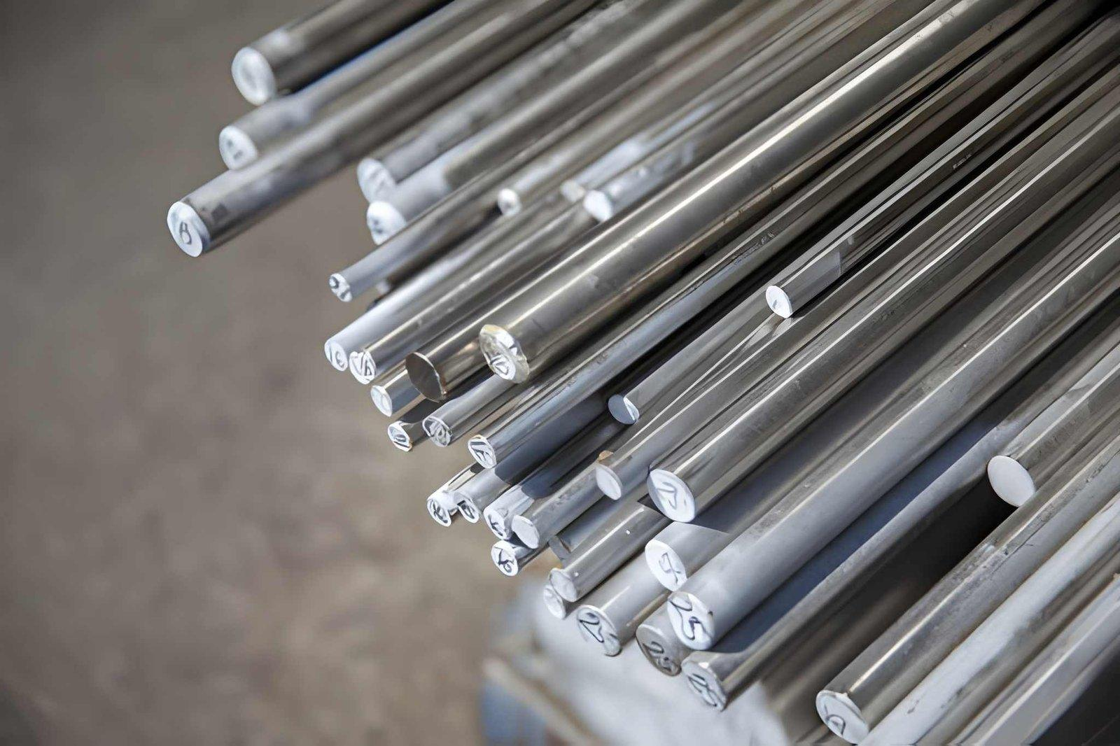
Common Steel Grades Options
| Material | Characteristics | Application |
| Mild Steel (1018 / 1020) | Easy to machine, low carbon | General components |
| Alloy Steel (4140 / 4340) | High strength and toughness | Mechanical parts under load |
| Tool Steel (D2 / H13) | High hardness and wear resistance | Dies and tooling |
| Stainless Steel (304 / 316) | Corrosion resistance | Harsh environments and hygiene applications |
Dimensional Accuracy and Tolerances
Steel is quite challenging; however, it allows tighter tolerances when machined correctly. In general, the achievable tolerances depend on part size, geometry, and setup rigidity.
At Sochain Precision, we maintain accuracy by controlling machine calibration, tool condition, and cutting parameters.
| Feature Type | Achievable Range |
| Linear dimensions | ±0.01 mm to ±0.05 mm |
| Hole diameters | ±0.01 mm to ±0.03 mm |
| Flatness | 0.01 mm to 0.03 mm |
| Surface finish (machined) | Ra 0.8 to 3.2 µm |
Tighter tolerances may require additional operations such as grinding and secondary finishing, like anodizing, painting, powder coating, etc.
Machining Operations for Steel Parts
Our facility is equipped with modern CNC machines to match customers' unique demands and meet constrained deadlines. We decide on techniques considering your design intent and the part's intended use.
Here are the machining options available at our facility.
CNC Milling
Milling is primarily used to produce flat surfaces, pockets, and contoured features. It provides high precision and accuracy and allows the controlled material removal from a workpiece, utilizing predefined tool paths.
Typically, we use end mills. These comprise predetermined "step down" and "step over" values so that there is an optimal relationship between the amount of material removed from the workpiece (to achieve the desired shape) and the surface finish.
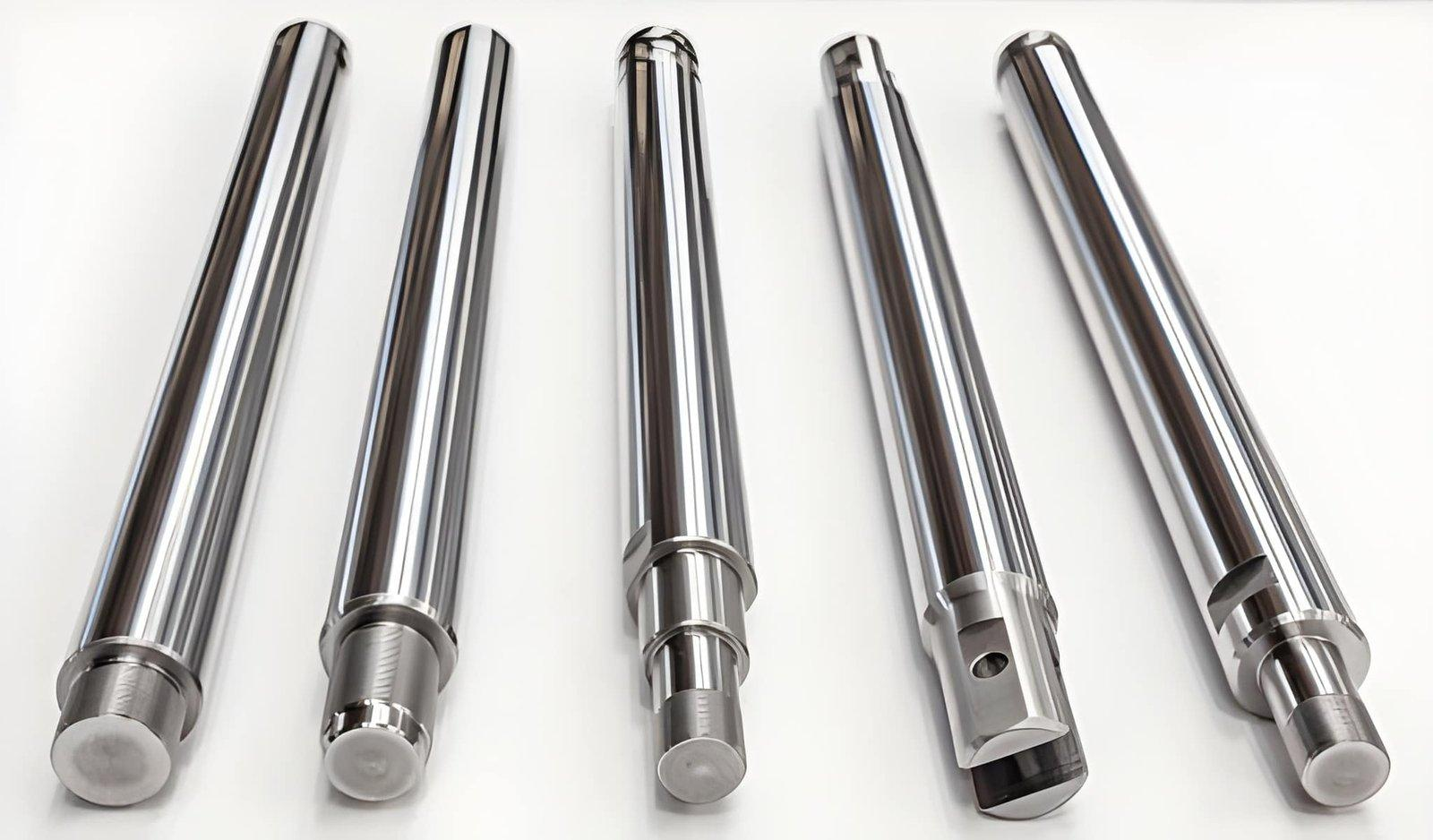
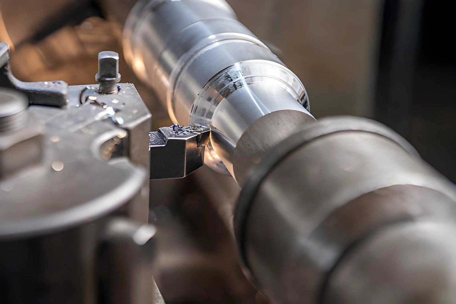
CNC Turning
Turning is utilized to create cylindrical-shaped components, i.e., shafts and bushings. In operation, the workpiece rotates about its axis as the cutting tool removes material.
Turning features high concentricity and helps achieve thread precision. Therefore, it is notably a good option when creating parts that are symmetrical around their axis.
Drilling and Tapping
Through drilling and tapping, we produce holes at precise diameters and alignments. We use tapping to create internal threads on the part for fastening purposes.
Drilling outcome usually depends on the speed. While clean internal threads depend on proper feed rate and adequate tap selection.
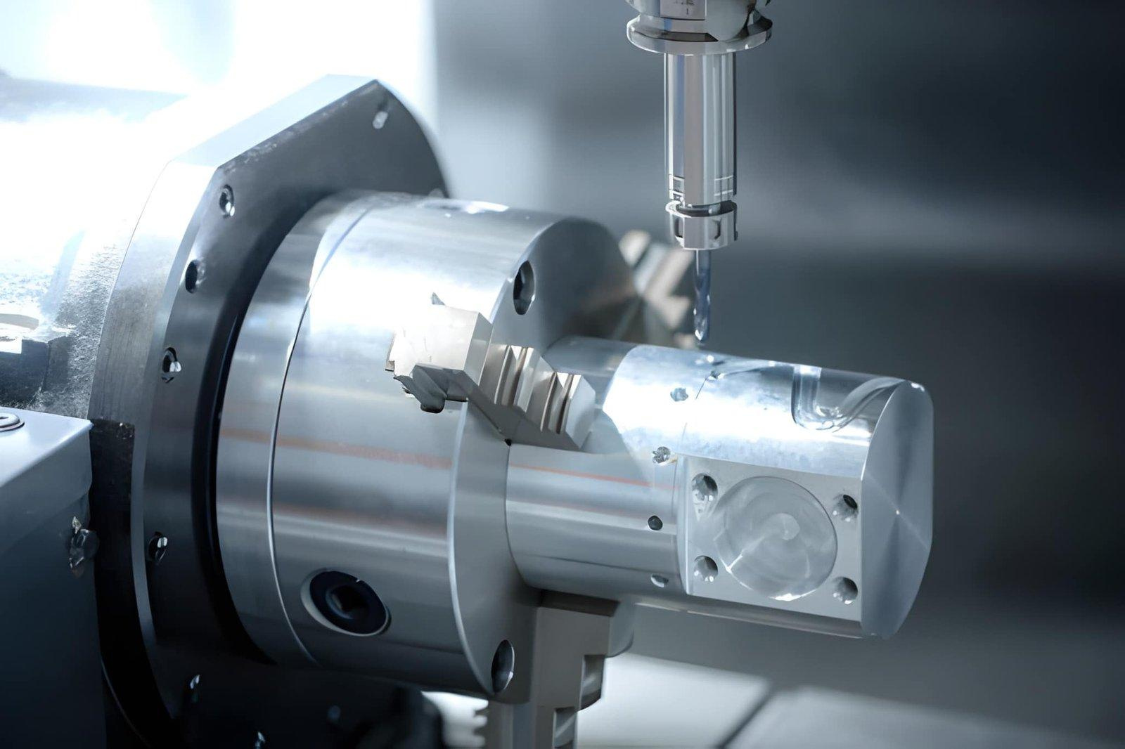
Multi-Axis Machining
For complex or intricate shapes, we use multi-axis machining centers. This allows us to machine all sides of an angled surface without requiring additional setup operations.
Moreover, it helps us eliminate positioning errors associated with repositioning operations and maintain the part's orientation throughout the operation.
Surface Finishing Options
Steel parts often require further finishing after machining to meet functional and enhanced corrosion protection.
| Process | Purpose |
| Deburring | Removes sharp edges after machining |
| Grinding | Improves dimensional accuracy and surface finish |
| Polishing | Reduces surface roughness |
| Coating (Plating/Painting) | Adds corrosion resistance |
Our team select finishing option based on how the part will be used. Functional parts may require minimal finishing, while exposed components may need coating or polishing.
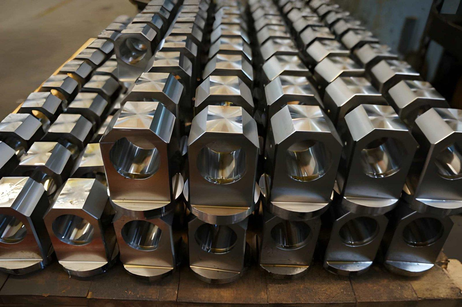
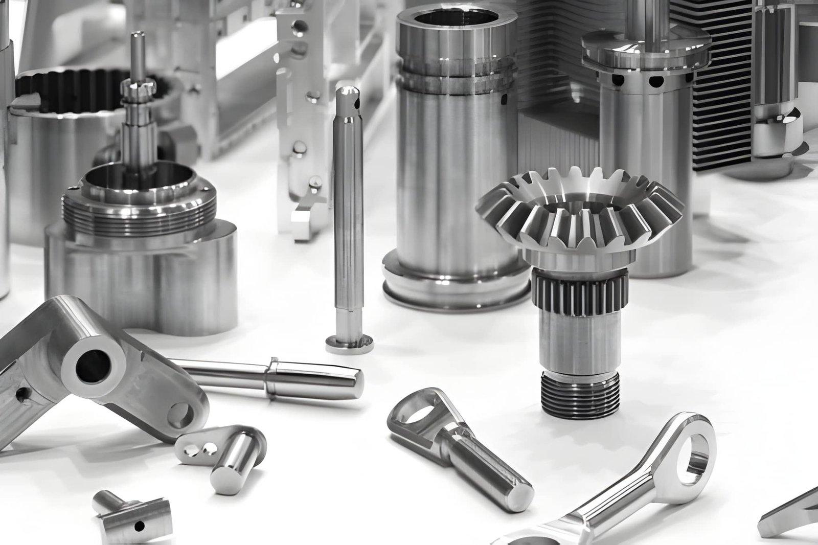
Applications of CNC Steel Cutting
Steel machining is used in industries where strength and durability are required.
- Mechanical and Industrial Parts: We machine gears, shafts, brackets, and load-bearing components. These parts must handle mechanical stress without deformation.
- Tooling and Dies: Steel is used for dies, molds, and cutting tools. Tool steel grades provide the hardness required for repeated use.
- Automotive Components:We machine engine components, mounting systems, and transmission parts. These parts require precision and fatigue resistance.
- Structural Components:Steel is used for frames, supports, and heavy-duty assemblies. These components must maintain strength under continuous load.
Design Considerations for Steel Machining
Decisions made by designers determine how easily steel may be machined.
Each design we review has three aspects to consider: structural strength, tool accessibility, and machining stability.
Designs well-suited for machining will have less tool wear, reduced vibrations, and improved surface finish.
Wall Thickness and Structural Stability
The wall thickness of a part must withstand the forces produced by the cutter during machining.
Thin-walled structures tend to flex or vibrate under load, especially in steel.
As such, we suggest a wall thickness of at least 3 to 5mm as a bare minimum for good stability.
For structures designed to carry loads, thicker walls (6 to 10mm) provide optimal stiffness.
Long, thin-walled sections unsupported during machining can bend significantly due to the load from the cutting action.
Proper wall thickness allows us to improve our feed rates and tool sizes.
This increases both our machining efficiency and reduces the overall time of production.
Internal Corners and Tool Access
Sharp internal corners create high stress concentrations within the part and create significant machining difficulties.
Standard cutting tools do not produce a perfect "sharp" internal edge.
Therefore, we add radii (R1-R5 mm) to internal corners wherever practical.
Large radii are enough to accommodate standard end-mills
Small radii require small tools and often result in reduced cutting speeds
The addition of radii improves tool life and allows smoother motion for the tool.
This results in increased tool life, better surface finish, and more stable machining.
Tool Reach and Deep Feature Design
Deep pockets or cavities require long tools to reach into those areas.
Decreasing the rigidity of long tools causes vibration or tool deflection.
In order to prevent excessive deflection, it is recommended to limit the depth-to-diameter ratio to 3:1 or less if possible.
Instead of one deep cut, use stepped cuts; this eliminates extreme tool deflection in some cases.
Avoid creating deep, narrow pockets that severely restrict tool travel.
When necessary due to deep features, we will alter the machining path and/or machining strategy.
However, improving the design maintains accuracy and surface finish quality.
Hole Design and Tolerances
When producing holes in steel, there are two considerations: tool size and subsequent finishing operations.
Either undersizing or oversizing holes will affect assembly fit.
Typical drilling tolerance ranges are ±0.01 mm to ±0.03 mm.
Provide clearance for threaded or press-fit components.
Use a chamfer (0.5 to 1 mm) to improve assembly fit and eliminate burrs.
We will position the holes correctly relative to your CAD model to ensure accurate positioning of holes.
Accurate hole placement greatly improves assembly performance and minimizes rework.
Feature Spacing and Machining Clearance
Too much proximity between features creates difficulty for tool access and material stability.
Sufficient spacing allows for efficient cutting while minimizing tool conflict.
Minimize feature spacing to at least twice the diameter of the largest tool used in processing. Do not place deep features near edges.
Provide sufficient clearance for tool entry and exit
Optimal spacing maximizes toolpath efficiency and reduces total machining time.
It ensures consistency in surface quality between features.
Surface Finish and Machining Strategy
Surface finish is determined by the selected cutting tool(s), feed rate(s), and machining pass strategy.
Design elements of a product can also affect how a surface is processed.
To obtain fine finishes requires smaller step over values (0.1 to 0.3 mm).
Roughing passes are best suited for removing bulk amounts of material efficiently.
Finishing passes optimize final surface quality.
Based upon your desired finish specifications, we develop a pass-by-pass machining process plan.
Designing with finishing parameters in mind enables us to consistently deliver good surfaces.
Why Work With Our CNC Steel Machining Services
We approach steel machining with a focus on process control and engineering precision. Our team evaluates each project before machining to ensure stability and manufacturability.
We use structured workflows similar to established machining providers, focusing on repeatability and quality control. At the same time, we provide design feedback to help reduce machining challenges in later production.
Our setup allows us to handle both prototype and production work with consistent results. CNC steel cutting is suitable when strength, accuracy, and durability are critical to your part. With proper design and controlled machining, you can achieve reliable performance across different applications.
We review each design before production and guide you with practical design recommendations. If you have a CAD file, you can send it to us for evaluation and a detailed machining plan.
FAQs
Wall thickness directly affects machining stability and part strength. For most steel components, we recommend a minimum wall thickness of 3 to 5 mm. This allows maintain rigidity during cutting, because thinner walls can flex under tool pressure, especially in higher-strength steels.
For parts under load or with long spans, increasing the thickness to 6 to 10 mm improves stability and reduces the risk of vibration or deformation. We review your design and suggest adjustments if the walls may affect machining performance.
The internal radii help facilitate the uniform movement of cutting tools through the workpiece. The round nature of the CNC cutting tools prevents them from creating an ideal sharp corner internally; adding a radius helps improve machining efficiency and accuracy.
As a rule of thumb, it is recommended to use radii of R1-R5 mm based on the tool type being used and how deep you want your feature to be. Using a smaller radius requires a smaller diameter cutting tool; this will result in slower speeds of cutting and increased machining time. Adding appropriate radii to your part will also eliminate excessive stress concentrations when machining the final product.
Optimal tool reach determines the hole depth. If the holes need to go too far into a part, we normally use longer tools. These tools typically reduce rigidity and impact the surface finish quality.
Following the best design practices with tool reach, we limit our depth-to-tool-diameter ratios to 3:1 or less. If part features exceed this ratio, we will alter the way we program the toolpath or provide guidance on redesigning the geometry of the part itself by breaking up the feature into stepped sections.
Start Manufacturing Your Custom Parts Now!
Understanding Your Goals, Delivering Your Solutions – We’re Committed to Making CNC Machining Simple and Stress-Free!