 (+035) 527-1710-70
 NEWSLETTER

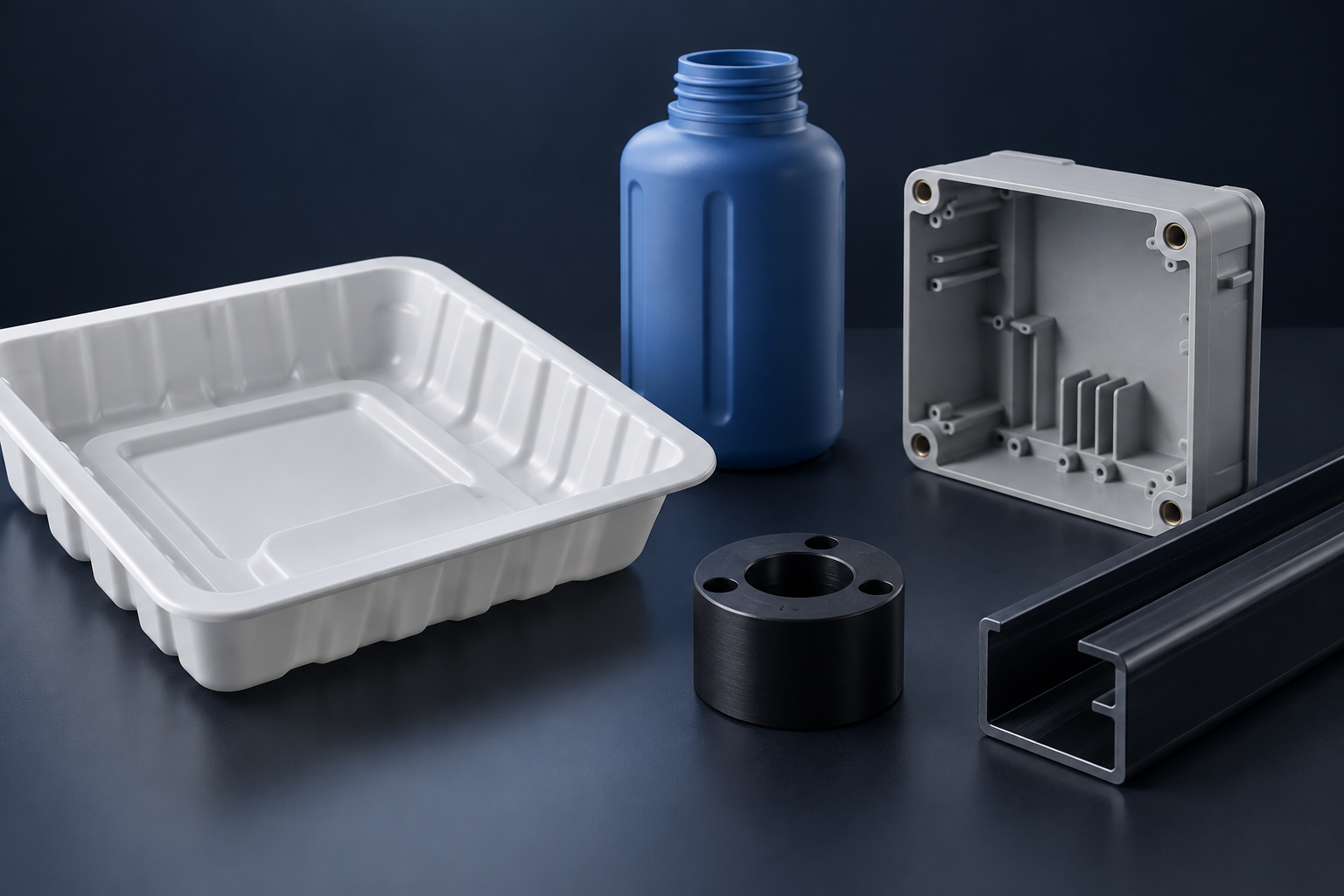
Plastic forming and manufacturing processes suit different shapes, materials and production volumes. Injection molding excels at detailed repeat parts. Extrusion suits continuous profiles. Thermoforming suits sheet-based shells. Choose the process around your geometry and commercial requirements before committing to tooling.
1. Injection Molding For Detailed Repeat Parts
Injection molding fills a closed mold with molten polymer to produce repeatable component geometry.
You can integrate ribs, bosses and assembly features into one part. However, draft, wall transitions and gate positions need early review. Thick sections can increase cooling demands and create sink or internal defects.
This route becomes attractive when repeat demand justifies tooling. Review Sochain’s injection molding service when your design is approaching production.
2. Extrusion For Continuous Profiles
Extrusion pushes softened polymer through a die to create a continuous cross-section.
Choose it for tubing, channels and long profiles. You then cut the extrusion to length. Drilling or machining can add local features afterward.
A profile with frequent cross-section changes may need another route. Also consider straightness, cooling distortion and how cut lengths will be measured.
3. Blow Molding For Hollow Containers
Blow molding inflates a heated polymer form inside a mold to create a hollow part.
It suits bottles, reservoirs and certain ducts. Several variants exist, including extrusion blow molding and injection stretch blow molding. Their material and geometry requirements differ.
Your review should address wall distribution, neck accuracy, parting features and leak testing. A hollow shape alone does not prove that any blow molding variant will work.
4. Thermoforming For Trays And Shells
Thermoforming stretches heated plastic sheet over or into tooling.
Vacuum or pressure helps shape the sheet, which is trimmed afterward. You can use it for trays, guards and equipment covers. Deep draws and sharp transitions can thin the material unevenly.
Decide which surface must match the tool accurately. Also include trimming, mounting holes and assembly edges in the cost comparison.
5. Rotational Molding For Large Hollow Parts
Rotational molding heats polymer inside a rotating mold to form hollow components.
It often suits tanks and large housings where generous radii are acceptable. Heating and cooling cycles influence productivity. Tight local interfaces may need secondary machining or inserts.
The British Plastics Federation rotational molding group provides an industry reference for this process sector.
6. Compression Molding For Charged Materials
Compression molding shapes a measured charge between heated mold surfaces under pressure.
It is used with suitable thermosets, elastomers and composite molding compounds. Cure requirements and charge placement influence the finished part. You should review flash, trimming and material flow around inserts.
Do not treat every compression-molded material as remeltable. Thermoset curing differs fundamentally from thermoplastic cooling.
7. CNC Machining For Stock-Based Components
CNC machining cuts a plastic part from stock without a dedicated forming mold.
Strictly speaking, it is a subtractive manufacturing route rather than a forming process. It belongs in your comparison because it can avoid tooling during development or limited production.
You gain flexibility for design changes, but tool access limits internal shapes. Stock properties also differ from the effects of molding flow. Specify the material form when your test depends on those differences.
Compare Complete Manufacturing Routes
Compare tooling, secondary work and acceptance testing together instead of comparing machine cycle times alone.
| Your Part | Route To Evaluate First | Main Purchasing Question |
| Detailed enclosure with bosses | Injection molding | Will demand recover tooling investment? |
| Constant-section channel | Extrusion | Which features need secondary work? |
| Hollow bottle | Blow molding | How will wall distribution be checked? |
| Thin equipment cover | Thermoforming | Which face controls assembly fit? |
| Large tank | Rotational molding | What leak and fitting tests are required? |
| Thermoset electrical component | Compression molding | Which cure and material controls apply? |
| Small batch of precision spacers | CNC machining | What conditioning defines final size? |
Separate Geometry Constraints From Volume Economics
Eliminate unsuitable processes by geometry before comparing their production costs.
A continuous extrusion cannot directly create a different cross-section every few centimeters without additional operations. A thermoformed sheet cannot reproduce every internal rib arrangement of an injection-molded enclosure. CNC machining needs cutter access to the material being removed.
Start with a simple geometry description: open shell, closed hollow part, constant profile or solid component. Then identify enclosed passages, undercuts, mounting interfaces and cosmetic faces. This creates a useful shortlist without relying on a vague “low-volume” label.
Next, compare the forecast. Include annual demand, release size, expected design changes and program life. A large annual order split into many small releases creates different handling requirements from one uninterrupted production run.
Calculate A Tooling Break-Even Without Guessing Prices
A simple break-even calculation helps compare routes when you already have credible quotations.
Let one route have tooling cost T₁ and recurring accepted-part cost C₁. Let the alternative have T₂ and C₂. Assume the second route has higher tooling but lower recurring cost. Then calculate Q = (T₂ − T₁) ÷ (C₁ − C₂).
Q is an illustrative break-even quantity under the stated assumptions. It does not include every commercial risk automatically. Tool maintenance, changes, storage, inspection and delivery can alter the result. Use consistent scope and currency for both quotations.
The denominator also deserves attention. If recurring costs are nearly equal, the calculated quantity becomes highly sensitive to small estimating errors. In that case, flexibility and delivery may matter more than a precise-looking result.
Do not use this formula to decide whether the geometry is suitable. A financially attractive process still fails if it cannot produce the required features or material behavior.
Compare The Same Enclosure Across Three Routes
An enclosure comparison becomes useful when each route is allowed a suitable design.
Consider a protective cover with mounting holes and moderate cosmetic requirements. A machined version may suit early interface testing. A thermoformed version may use a sheet-based shell with trimmed edges. An injection-molded version may integrate bosses and ribs.
| Decision | Machined Version | Thermoformed Version | Injection-Molded Version |
| Starting material | Solid stock | Sheet | Resin pellets |
| Geometry priority | Tool access | Draw and trimming access | Filling, cooling and ejection |
| Assembly features | Machined directly where accessible | Often trimmed or added separately | Can be integrated when designed appropriately |
| Design changes | Review machining program and fixtures | Review forming and trim tooling | Review mold modification |
| Validation concern | Stock behavior | Wall distribution | Flow, shrinkage and local molding effects |
A direct conversion of one model into all three routes may be inefficient. Ask for process-specific design review while preserving the interfaces and functions that must remain fixed.
Define The Material Beyond Its Family Name
Your process review needs a resin grade and performance requirements, not just a polymer abbreviation.
An impact-modified grade can differ from an unmodified grade. Reinforcement changes behavior and may affect the manufacturing route. Colorants and other additives can also influence appearance and performance.
Specify what the finished component must do. Include temperature, chemical contact, loading and any required certification. Let the material documentation and validation support the final selection.
A prototype made from stock can be useful without reproducing molded properties exactly. State what the prototype is intended to validate. This prevents a successful fit check from being mistaken for full material qualification.
Plan Acceptance Before Tooling Approval
Tooling approval should follow agreed dimensional, cosmetic and functional evidence.
Identify critical dimensions and when they will be measured. Define relevant conditioning and assembly tests. Approve cosmetic samples under consistent viewing conditions. If a part contains inserts, include their position and retention requirements.
Discuss tool ownership and the records needed for future production. Confirm how design changes will be controlled and how replacement tooling will be validated. These questions belong in the initial comparison because they affect the cost of the complete program.
Separate Shape Feasibility From Production Economics
You should eliminate unsuitable forming routes before comparing tooling and unit costs.
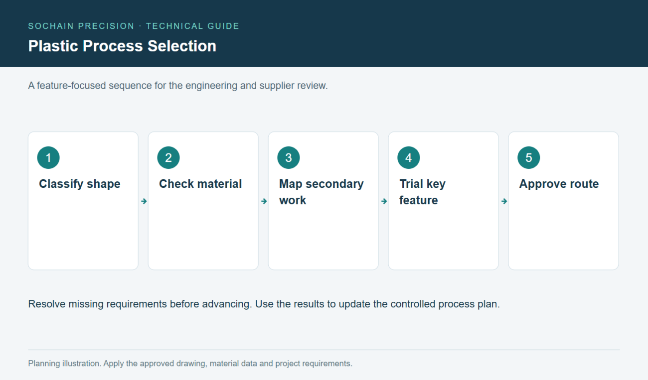
Plastic Process Selection. Follow the sequence while resolving project-specific requirements.
Begin with the part’s basic shape. A continuous profile suggests extrusion. A hollow container suggests a blow-molding review. A shallow open shell may suit thermoforming. These are starting points, not automatic process selections.
Next examine the details that each route must reproduce. Internal bosses, enclosed undercuts and local wall changes may require redesign or secondary work. A low forming cost can lose its advantage when extensive trimming and machining follow.
Material compatibility comes next. A polymer family may exist in grades developed for different processes. Do not assume an available extrusion grade will behave like a selected injection grade.
Finally compare the production program. Consider annual demand, expected design changes, tooling ownership and spare-tool requirements. A process suited to stable repeat production may be inconvenient during frequent revisions.
Use this order to avoid a common purchasing mistake. A quotation for an unsuitable route can look attractive because essential features were excluded. Confirm the complete delivered geometry before comparing prices.
Include Secondary Operations In The Process Map
You should evaluate forming, trimming, joining and inspection as one manufacturing route.
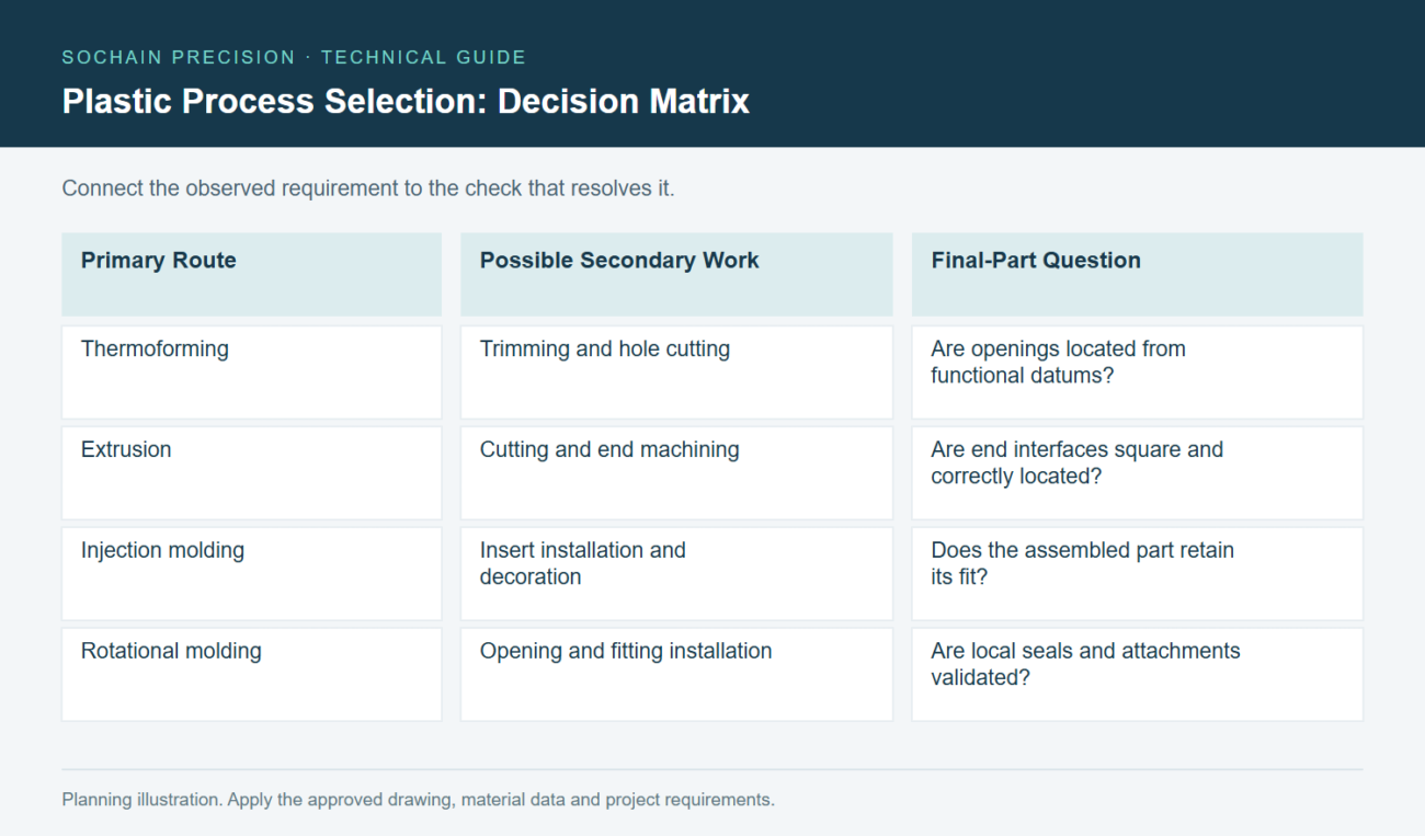
Plastic Process Selection: compare the requirements and checks discussed in this article.
A thermoformed cover may leave the forming operation with a surrounding sheet flange. Trimming establishes its final outline and openings. Your assembly datums must remain meaningful across both operations.
An extruded profile may require sawing, drilling and end machining. Those operations determine length and interface quality. The extrusion alone cannot establish their acceptance.
A molded housing may need inserts, printing or welded subassemblies. Heat, clamping or local loading during those steps can affect its final condition. Inspect important features after the last relevant operation.
| Primary Route | Possible Secondary Work | Final-Part Question |
| Thermoforming | Trimming and hole cutting | Are openings located from functional datums? |
| Extrusion | Cutting and end machining | Are end interfaces square and correctly located? |
| Injection molding | Insert installation and decoration | Does the assembled part retain its fit? |
| Rotational molding | Opening and fitting installation | Are local seals and attachments validated? |
Ask suppliers to identify outsourced steps when they affect schedule or acceptance. Ownership of the overall route should remain clear. Otherwise, a defect at an interface can become a dispute between separate processors.
Validate The Process With A Representative Feature
You should choose trial features that reveal the main uncertainty in your proposed manufacturing route.
For injection molding, a trial might focus on a thin flow path or critical clip. For thermoforming, investigate material distribution around a deep corner. For extrusion, examine profile stability and the interfaces created by subsequent machining.
These examples are planning aids. The exact trial depends on geometry, material and equipment. Agree the question and acceptance method before producing samples.
Measure more than the easiest external dimensions. A container can match its outline while containing unsuitable local wall distribution. A housing can match its mounting pattern while a snap feature behaves inconsistently.
Keep process-relevant information with the samples. Material identification, tool revision and conditioning can explain differences between otherwise similar parts. Without those records, a successful sample may be difficult to reproduce.
When you compare two routes, test the functions both must deliver. Do not favor one route by giving it a less demanding test. Record any intentional difference in material or wall design.
The result should support a process decision. It should also identify requirements that need further tooling or production validation.
Plan For Tool Changes And Product Revisions
You should consider likely design revisions before committing to a forming tool.
A product under development may change connector openings, mounting features or its external envelope. Those changes have different consequences for a mold, forming tool or extrusion die. Ask which dimensions remain practical to modify.
Separate stable features from uncertain features in the design review. Where appropriate, leave uncertain interfaces for replaceable tooling details or secondary machining. The supplier must assess whether that approach suits the selected process.
Confirm who owns the tooling and its controlled design information. Specify how revisions are identified and how obsolete samples are separated. A tool modification without corresponding drawing control can create two apparently valid product definitions.
Evaluate maintenance and replacement planning for continuing production. Wear-sensitive details may need attention before the overall tool requires replacement. Your inspection plan should detect changes that matter to assembly.
A useful process choice therefore considers the entire product program. Initial tooling cost matters, but revision flexibility and complete-part consistency can matter more over time.
Frequently Asked Questions
Your forecast and material specification should guide the final process decision.
Which Process Is Cheapest?
There is no universal winner. Compare total program cost at your actual quantity and revision frequency.
Can One Part Use Several Processes?
Yes. You might mold a blank, machine a sealing interface and install inserts afterward.
What Should A Molding Enquiry Include?
Request a quote with CAD, resin requirements, annual volume, program life and cosmetic acceptance criteria.