 (+035) 527-1710-70
 NEWSLETTER

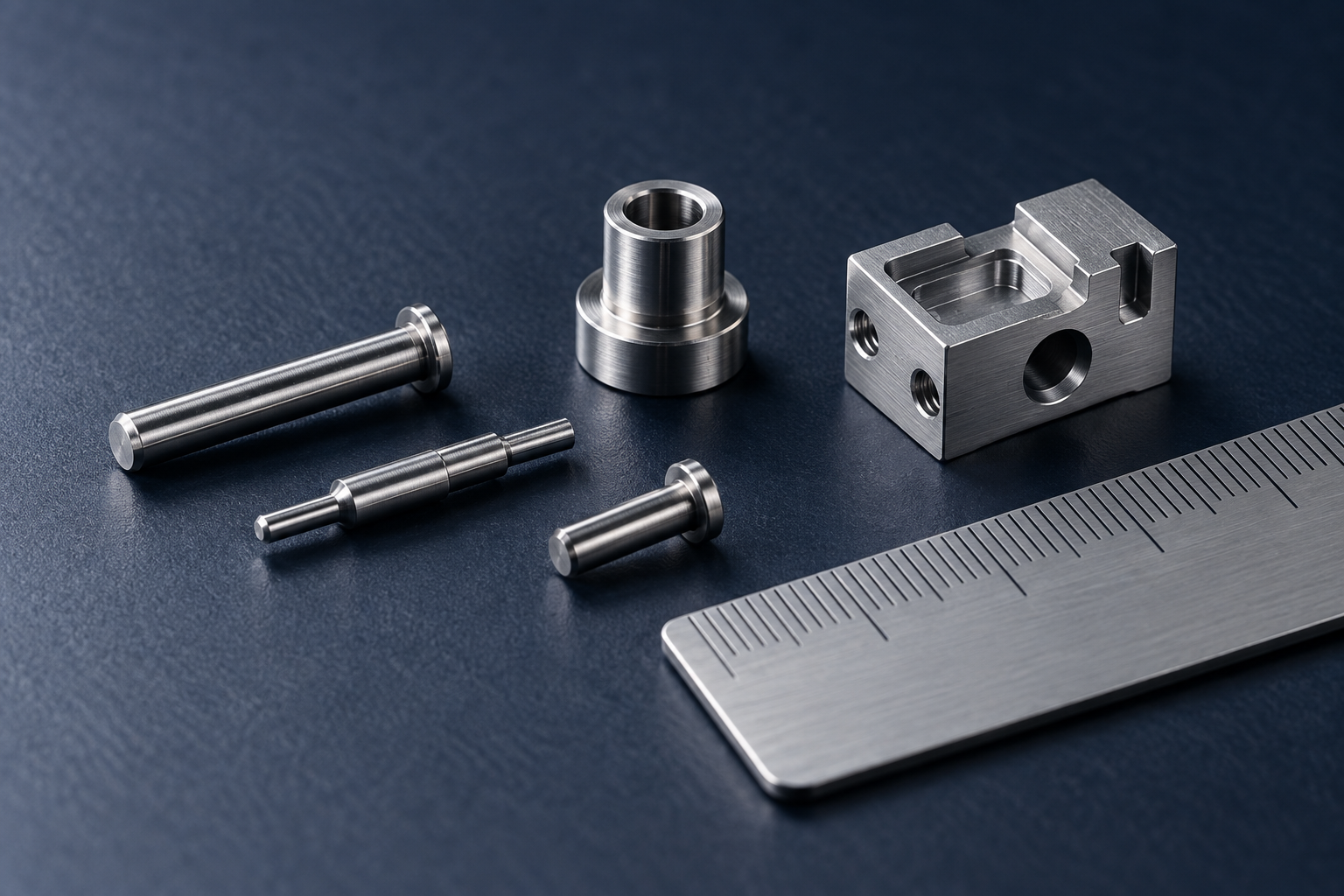
Miniature machining produces small parts or fine features using appropriately scaled tools, fixtures and inspection methods. Small size alone does not define difficulty. A shallow miniature pocket can be easier than a long, slender pin with a demanding straightness requirement.
What Makes Miniature Machining Different?
Miniature machining becomes demanding when tool size, feature size and allowable error approach similar scales.
Tool runout that seems minor in conventional milling can load one cutting edge disproportionately on a small cutter. Harvey Tool’s miniature milling guidance discusses this sensitivity. Workholding force can distort a delicate part. Burrs can obstruct an opening rather than merely affect its appearance.
There is no single universal size boundary between conventional, miniature and micro machining. Describe your actual dimensions instead of relying on the label.
Choose The Process Around Feature Access
Match the machining method to geometry, material and how the part can be held.
| Feature Or Part | Route To Evaluate | Main Constraint |
| Small rotational component | Precision turning | Grip length and tool access |
| Long slender pin | Swiss-type turning | Bar quality and support configuration |
| Fine pocket or external contour | Micro milling | Cutter reach and runout |
| Very narrow conductive-metal slot | EDM | Electrode access and surface requirements |
| Small hole | Micro drilling or another qualified route | Depth, evacuation and inspection |
Swiss-type machines use sliding-headstock configurations for small-part work. Tsugami’s machine overview describes that equipment category. It does not establish which machine a particular supplier owns.
Design Features That Can Be Produced Reliably
Give small tools and inspection equipment enough access to reach the critical feature.
Keep internal corners compatible with the selected cutter. Reduce unnecessary cavity depth. Where practical, leave a robust holding feature that can be removed later. Discuss whether the part will remain attached to bar stock until final operations.
Specify edge conditions by function. “Remove all burrs” may be insufficient for a fluid passage or electrical contact. Define acceptable edge breaks without erasing a tiny functional land.
An illustrative example is a pin with a cross-hole near its tip. The hole may be machinable, yet deburring its internal intersection may dominate the process. Review that intersection before approving the design.
Plan Inspection Before Cutting
Your measurement method must resolve the feature without deforming or obscuring it.
An optical system may measure a visible profile but miss an internal burr. A contact probe may not reach a narrow cavity. A functional gauge may confirm assembly while revealing little about an individual geometric error.
Ask how each critical requirement will be verified. Agree whether destructive sectioning, sampling or specialized inspection is necessary. Record the uncertainty and limitations relevant to acceptance.
Packaging belongs in this discussion. A measured component can still bend, scratch or disappear during washing and shipment. Define separation, identification and handling requirements.
Understand The Real Cost Drivers
Setup, handling and verification can cost more than the material in a miniature part.
Tool replacement, interrupted production and rejected parts also matter. Avoid assuming that a smaller component must be cheaper. A slightly larger relief or more accessible hole may reduce cost without changing function.
Sochain advertises CNC machining services. Submit feature details for a specific feasibility review; miniature capability requires part-level confirmation.
For related background, see our CNC machining tolerances guide.
Tool Diameter Changes The Meaning Of Runout
The same absolute runout becomes more significant as the cutting tool becomes smaller.
Imagine 0.005 mm of runout as a simplified comparison. It is 0.05% of a 10 mm tool diameter. It is 1% of a 0.5 mm tool diameter. These figures illustrate scale; they are not recommended operating limits.
The effect also depends on cutting-edge geometry and chip thickness. One edge may carry more load than another. A nominal feed calculation therefore cannot establish reliable cutting without considering the assembled tool system.
Ask how the tool is held and checked. A high-speed spindle does not automatically solve runout or holder contamination. Short, well-supported tooling may contribute more than a higher advertised spindle speed.
Plan How The Part Will Be Held And Released
The manufacturing plan must support the component until its delicate features can survive handling.
Some miniature parts can remain attached to bar stock through several operations. Others need dedicated fixtures, soft jaws or temporary supporting features. The final cutoff or release can introduce a new burr or distortion risk.
Consider a tiny thin-walled sleeve. Strong clamping may improve stability during cutting but distort the wall. Light clamping may preserve shape but reduce resistance to cutting forces. The solution must be evaluated on the actual geometry.
Ask when final dimensions are measured relative to release from the fixture. Also identify how the component moves through cleaning and packaging. Bulk handling may be unsuitable when parts can interlock or damage one another.
Treat Burr Removal As A Designed Operation
Miniature deburring needs a defined result and a method that preserves the surrounding geometry.
At small scale, an edge break can remove a meaningful part of a sealing land or retaining feature. A process that produces an attractive exterior may leave a burr inside a cross-hole. Inspectability must therefore be considered before approving the deburring route.
| Feature | Deburring Concern | Acceptance Question |
| Tiny external shoulder | Edge rounding changes contact | What edge condition is permitted? |
| Cross-drilled passage | Hidden intersection burr | How will the internal intersection be checked? |
| Miniature thread | Entry damage or loose chips | Does the thread gauge and assemble correctly? |
| Thin slot | Burr closes useful opening | What clear opening is required? |
Avoid demanding a perfectly sharp edge and complete burr removal without defining an achievable condition. The drawing should distinguish functional sharpness from an uncontrolled cutting burr.
Match The Inspection Method To The Feature
A miniature inspection plan should explain what each method can see and what it cannot.
Optical measurement can work well for visible outlines. It may not characterize an obscured internal surface. Contact measurement can be useful where probe access and force are acceptable. Functional gauges can verify an interface but may combine several errors into one pass-or-fail result.
For critical features, ask the supplier to demonstrate the method before the full batch. A trial measurement can reveal an accessibility problem while the design is still changeable. It can also show whether a dedicated gauge would simplify repeat inspection.
Specify the relevant environmental and fixturing conditions. The reported number should correspond to the condition in which the drawing defines acceptance.
Compare Quotes Using Yield And Handling
The useful commercial metric is cost per accepted, undamaged component.
A low cycle-time estimate can overlook tool replacement, manual handling and verification. A more expensive fixture may reduce rejected parts or simplify inspection. Compare the complete route instead of treating setup as avoidable overhead.
Ask how the supplier plans to identify lots when individual marking is impractical. Include packaging requirements in the quotation. A component that passes inspection but arrives bent has not met the project’s objective.
For a new miniature design, consider a pilot batch with documented findings. Use it to confirm the process, inspection and handling sequence together. Then approve the repeat route against the released revision.
Build A Miniature-Part Error Budget
You should separate positioning, cutting, clamping and measurement effects when reviewing a miniature feature.
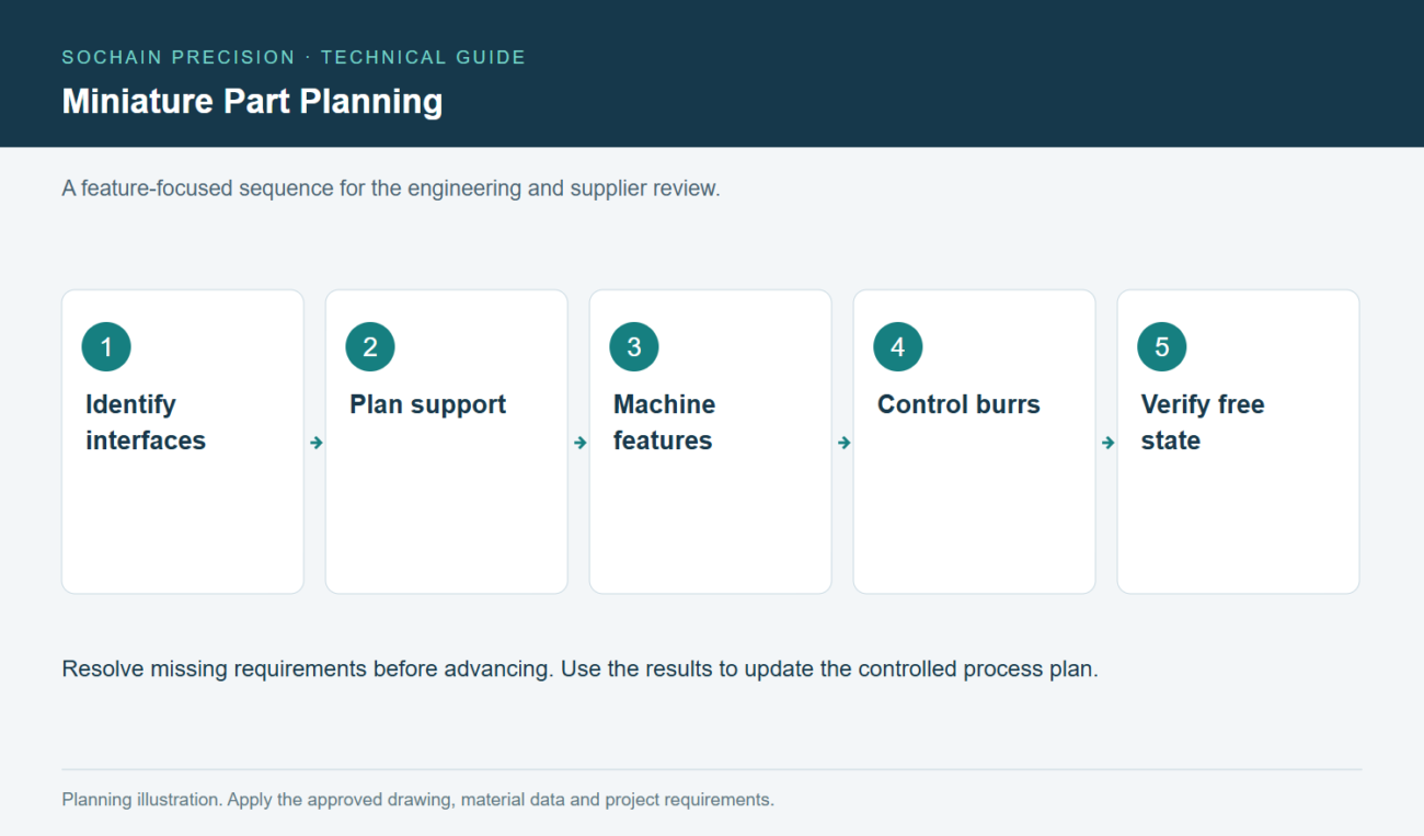
Miniature Part Planning. Follow the sequence while resolving project-specific requirements.
A small nominal dimension does not explain why a feature becomes inconsistent. Tool runout can change the effective cut. Workpiece movement can alter location. Burrs can change the apparent boundary measured by an optical system.
Start with the functional relationship. A miniature pin may need to enter a bore while maintaining alignment. Diameter alone cannot establish that relationship. Review straightness, location and the mating component where they matter.
Next identify how each feature is created and measured. A dimension transferred between setups may depend on locating repeatability. A thin feature measured under contact force may deflect. These effects belong in the planning discussion.
Do not assign arbitrary numerical allowances without process evidence. Ask the supplier to explain the dominant risks and proposed controls. Trial measurements can then show whether the planned approach is credible.
The purpose is practical prioritization. Spend effort on the effects that threaten function rather than tightening every drawing dimension equally.
Design Workholding Before Removing Support Material
You should preserve useful support until the operations needing that support are complete.
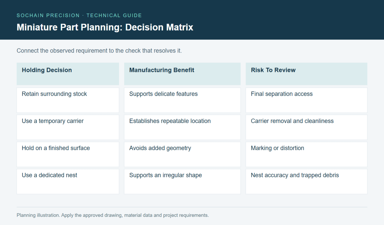
Miniature Part Planning: compare the requirements and checks discussed in this article.
A miniature component can become difficult to hold before it becomes difficult to cut. Removing all surrounding stock early may leave only fragile walls or finished surfaces for clamping. Plan the sequence around that constraint.
Temporary tabs, a sacrificial carrier or a suitable holding feature may simplify the route. Their suitability depends on the part and the removal operation. Agree which surfaces can carry witness marks after separation.
Consider the final release step explicitly. Cutting the last connection can move the part or create a burr on an important edge. Provide access for separation and subsequent inspection.
| Holding Decision | Manufacturing Benefit | Risk To Review |
| Retain surrounding stock | Supports delicate features | Final separation access |
| Use a temporary carrier | Establishes repeatable location | Carrier removal and cleanliness |
| Hold on a finished surface | Avoids added geometry | Marking or distortion |
| Use a dedicated nest | Supports an irregular shape | Nest accuracy and trapped debris |
Inspect relevant dimensions after unclamping. A compliant measurement under fixture load may not represent the free component. State the intended measurement condition when flexibility matters.
Make Burr Control Part Of The Feature Definition
You should specify edge acceptance in terms of function and inspection access.
A small burr can obstruct a miniature hole or interfere with an assembly. Aggressive removal can also round a necessary edge. “Deburr all edges” may not adequately communicate the balance.
Identify edges near fluid passages, sliding contacts and mating features. State any required edge break separately from surfaces that must remain sharp. Use the drawing convention appropriate to the product.
Discuss how inaccessible intersections will be checked. An external visual inspection cannot establish the condition of an internal cross-hole. The proposed method should match the risk and available access.
Consider cleanliness after deburring. Removed particles should not remain trapped in pockets or small passages. Define the required delivered condition and any evidence needed for acceptance.
Avoid importing requirements from a different application merely because the components look similar. A small decorative part and a small fluid-control component can need very different inspection plans.
Where a requirement cannot be measured reliably, revise the design or inspection method before production. An uninspectable instruction creates uncertainty rather than control.
Package Miniature Parts So Their Identity Survives
You should protect miniature parts against damage, mixing and loss throughout inspection and delivery.
Bulk packing can allow delicate features to collide. Separate cavities or suitable carriers may be appropriate. The chosen protection should support handling without contaminating critical surfaces.
Keep part identity connected to the container when direct marking is impractical. Separate revisions and material batches clearly. Similar-looking components can be difficult to distinguish after they enter one tray.
Define the counting method and expected package quantity. Receiving inspection should not require unnecessary repeated handling of every delicate feature. A practical pack supports both verification and assembly use.
For measured samples, preserve the link between each sample and its inspection record. If individual identification is impossible, agree a controlled position or container system. Do not imply individual traceability when only batch traceability exists.
Review the unpacking operation with the same care as packing. A component that requires forceful removal from protection may be damaged before assembly. The delivered solution should include safe access to the part, not merely a protective enclosure.
Frequently Asked Questions
You should confirm both machining access and inspection access before ordering miniature components.
Can Any CNC Machine Make Miniature Parts?
Some can, but suitability depends on tooling, runout, workholding, control and measurement capability.
Does A Small Part Automatically Need A Tight Tolerance?
No. Set tolerances from function and assembly requirements, not overall size alone.
What Information Helps A Feasibility Review?
Request a quote with CAD, magnified drawing details, material, quantity, edge requirements and critical inspection features.